
Plastic Injection Moulding. A Complete Guide to Part Design, Tooling and Manufacture.
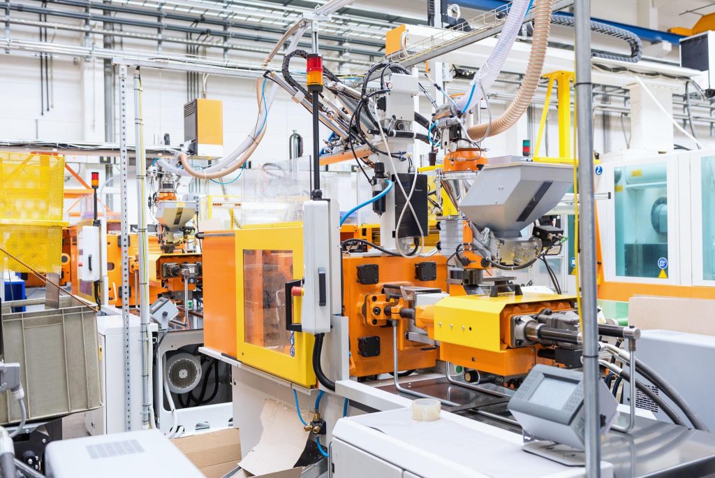
Plastic injection moulding is one of the most widely used manufacturing processes for producing high-quality plastic components in medium to high volumes. The process offers excellent repeatability, low unit costs at scale and the ability to create complex geometries that would be difficult or impossible to manufacture using other methods.
From consumer products and medical devices to automotive components and industrial equipment, plastic injection moulding is used across almost every sector of manufacturing.
Understanding how the process works and designing parts correctly from the outset can significantly reduce tooling costs, improve product quality and shorten development times.
How Plastic Injection Moulding Works
Injection moulding works by heating plastic granules until they melt and then forcing the molten plastic under pressure into a precision-engineered mould tool.
The mould contains a cavity that forms the external shape of the component and a core that creates internal features. Once the cavity is filled, the plastic is held under pressure while it cools and solidifies.
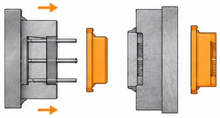
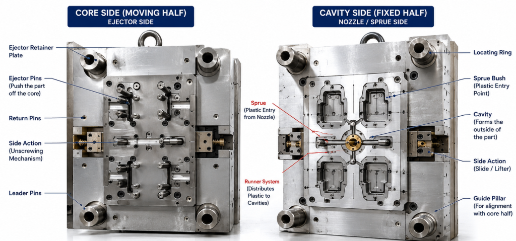
The mould tool is usually split into two halves:
- Fixed half (cavity side)
- Moving half (core side)
When the plastic has cooled sufficiently, the mould opens and the component is ejected using ejector pins located on the moving side of the tool.
The cycle is then repeated, allowing thousands or even millions of identical parts to be produced.
The Injection Moulding Cycle
A typical moulding cycle consists of four main stages:
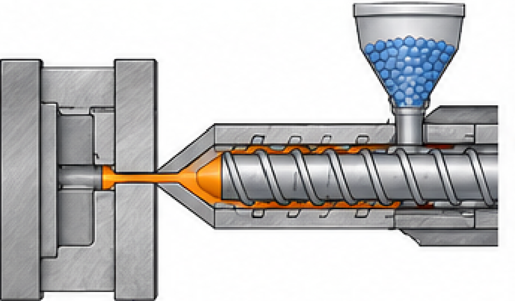
1. Injection
Plastic pellets are fed into a heated barrel where they are melted by a rotating screw. The screw then moves forward, injecting molten plastic into the mould cavity under high pressure.
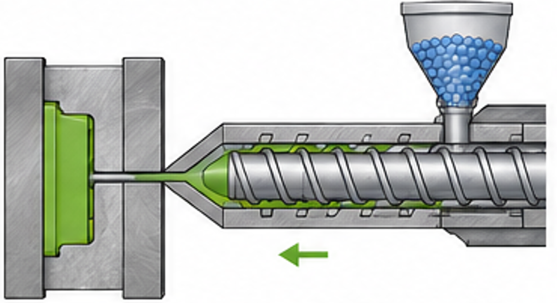
2. Packing and Holding
Once the cavity is filled, additional pressure is applied to compensate for material shrinkage as the plastic begins to cool.
This stage is critical for minimising voids, sink marks and dimensional variation.
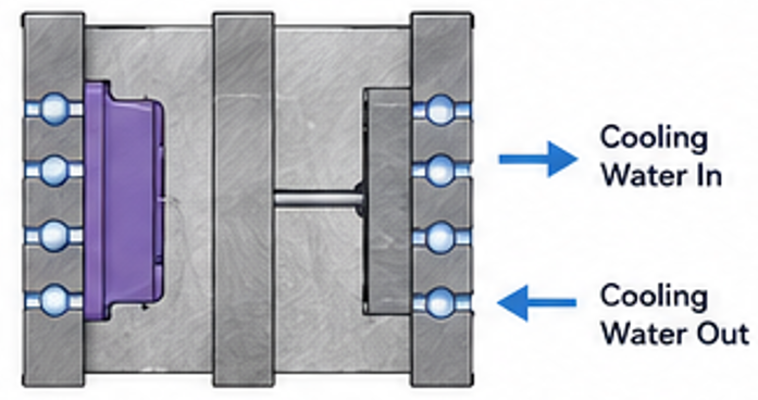
3. Cooling
Cooling channels machined within the mould circulate temperature-controlled water to remove heat from the plastic.
Cooling often represents the largest portion of the moulding cycle and has a major influence on production costs and part quality.
4. Ejection
After cooling, the mould opens and ejector pins push the component from the core side of the tool.
Good component design ensures that ejector pins are positioned in suitable locations where small witness marks will not affect product appearance or function.
Why Plastic Parts Shrink During Cooling
Most thermoplastics shrink as they cool from their molten state to room temperature.
As the material cools, the polymer chains move closer together, causing the overall dimensions of the component to reduce slightly.
Typical moulding shrinkage values range from approximately:
- ABS: 0.4% to 0.7%
- Polypropylene: 1.0% to 2.5%
- Nylon: 0.7% to 2.0%
- Polycarbonate: 0.5% to 0.7%
Toolmakers compensate for this by machining the mould cavity slightly larger than the required finished dimensions.
Accurately predicting shrinkage is a key part of injection mould tool design and often requires experience with the chosen material.
Best Practice Plastic Part Design
Good design for manufacture can dramatically reduce tooling costs while improving mouldability and part quality
1. Maintain Consistent Wall Thickness
One of the most important principles of injection moulded design is maintaining a consistent wall thickness throughout the component.
Large variations in wall thickness can lead to:
- Sink marks
- Warpage
- Internal stresses
- Longer cycle times
Uniform wall sections cool more evenly and produce more dimensionally stable parts.
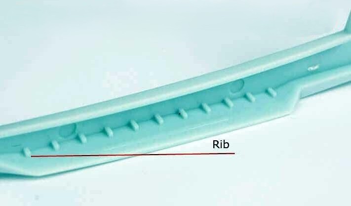
2. Use Ribs Instead of Thick Walls
Rather than increasing wall thickness to add strength, designers often use reinforcing ribs.
Ribs increase stiffness while minimising material usage and reducing cooling times.
As a general guideline, rib thickness should typically be around 50% to 60% of the adjoining wall thickness.
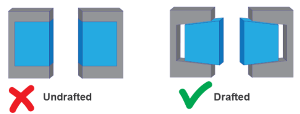
3. Add Draft Angles
Draft angles help components release from the mould during ejection.
Without sufficient draft, parts can stick to the tool, causing cosmetic defects or damage during ejection.
Typical draft recommendations are:
- 1° minimum on most surfaces
- 2° to 3° preferred on textured surfaces
- Greater draft on deep features
4. Include Generous Radii
Sharp corners create stress concentrations and restrict material flow.
Adding radii improves:
- Strength
- Mould filling
- Surface finish
- Tool life
Internal radii should generally be at least 50% of the wall thickness.
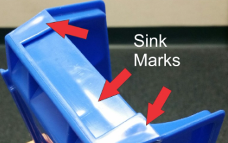
Understanding Sink Marks
Sink marks are shallow depressions that appear on the surface of moulded components.
They occur when thicker areas cool more slowly than surrounding material.
As the thicker section shrinks internally, the outer surface is pulled inward, creating a visible depression.
Common causes include:
- Excessive wall thickness
- Thick bosses
- Over-sized ribs
- Poor gate placement
Sink marks can often be reduced through better component design before tooling begins.
This is one reason why early involvement of an experienced product designer or design engineer can significantly improve moulding outcomes.
Bosses, Inserts and Fixing Features
Many moulded products require screw fixings, inserts or assembly features.
Bosses should be designed carefully to avoid creating thick material sections that may cause sinkage.
Typical best practice includes:
- Coring out large bosses
- Adding support ribs where necessary
- Maintaining uniform wall thickness
- Providing adequate draft
Threaded brass inserts can also be incorporated where higher fastening loads are required.
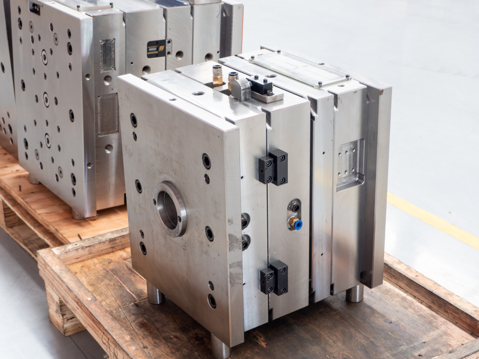
Injection Mould Tools
Injection Mould tools for high volume production
Production quality Injection mould tools are precision engineered assemblies with many moving parts and a cooling system. They are manufactured from hardened tool steel
A typical tool includes:
- Cavity inserts
- Core inserts
- Cooling channels
- Ejector system
- Guide pillars
- Sprue and runner system
- Gates
Tool complexity can range from simple prototype moulds producing a single component to highly automated production tools with multiple cavities.
Injection Mould tools for prototyping or low volume production
For early-stage projects and lower production volumes, aluminium tooling can provide a cost-effective alternative to hardened steel tools.
These are often referred to as prototype tools, bridge tools or soft tools.
Advantages and disadvantage of aluminium soft tools
Advantages
- Lower tooling costs
- Faster manufacture
- Easier modification during development
- Suitable for pilot production
- Reduced lead times
Disdvantages
- Shorter tool life
- More susceptible to wear
- Less suitable for abrasive materials
- Not ideal for very high production volumes
Aluminium tools are often an excellent option when validating a product before investing in full production tooling.
Manually Operated and Entry-Level Tools
For very low-volume production or product development work, simple mould tools can sometimes be used in manually operated moulding machines or small bench-top injection moulding systems.
These tools are generally simpler and less automated than full production moulds.
Benefits include:
- Low initial investment
- Fast prototype production
- Useful for concept validation
- Suitable for educational and development purposes
However, they typically have:
- Longer cycle times
- Reduced dimensional consistency
- Lower production rates
- Increased operator involvement
As demand increases, products are often transferred to fully automated production tooling.
Designing for Successful Injection Moulding
Successful injection moulded products begin with good engineering decisions at the design stage.
By considering wall thickness, draft angles, ribs, bosses, shrinkage and tooling requirements from the outset, manufacturers can avoid many common moulding problems while reducing overall development costs.
Whether producing a prototype using an aluminium tool or manufacturing hundreds of thousands of components from hardened steel production tooling, careful design for manufacture remains one of the most important factors in achieving a successful outcome.
At i-design, we provide product design, 3D CAD modelling, design for manufacture and injection moulding development support, helping clients take products from concept through to production-ready tooling and manufacture.
Fast Response
From brief to prototype in as little as 24 hours.
Highly Competitive
My charges are among the most competitive.
Experience
Over 25 years of expertise in product development and design.
Innovation
My designs consistently exceed client expectations.